Solving HTB Cyber Apocalypse Hardware challenges without any prior knowledge of hardware

A couple days ago I was playing and competition is really fierce, in order to squeeze the last bit of points I have to solve the hardware challenges. Unfortunately, I have no experience whatsoever in hardware, thankfully I ended up solving all of the hardware challenge and I think it is a very fun learning process. I will try to walk you through from knowing absolutely so everyone can follow along.
In this writeup I will talk about 3 challenges, Rids, The PROM, and Flash-ing Logs . The other 2 challenges were labeled very easy and I think there are a lot of learning resource already
Rids

In this challenge, we are given a client.py file that can be used to communicate to a hardware, in the description, we know it is W25Q128, I don’t even know what that is, so let’s try googling it

Okay, to be honest there are a lot of stuff here that I don’t understand, but for know all we know that it is a serial flash memory, let’s see what that means

Ah interesting, so it is a memory that we can communicate with, the objective of this challenge is not clear yet, but for now since it stores some data the first intuitive thing to do is to try to read it so lets try!
Thankfully we are given this client.py file that we can use to exchange information with the hardware
import socket
import json

def exchange(hex_list, value=0):

    # Configure according to your setup
    host = '127.0.0.1'  # The server's hostname or IP address
    port = 1337        # The port used by the server
    cs=0 # /CS on A*BUS3 (range: A*BUS3 to A*BUS7)

    usb_device_url = 'ftdi://ftdi:2232h/1'

    # Convert hex list to strings and prepare the command data
    command_data = {
        "tool": "pyftdi",
        "cs_pin":  cs,
        "url":  usb_device_url,
        "data_out": [hex(x) for x in hex_list],  # Convert hex numbers to hex strings
        "readlen": value
    }

    with socket.socket(socket.AF_INET, socket.SOCK_STREAM) as s:
        s.connect((host, port))

        # Serialize data to JSON and send
        s.sendall(json.dumps(command_data).encode('utf-8'))

        # Receive and process response
        data = b''
        while True:
            data += s.recv(1024)
            if data.endswith(b']'):
                break

        response = json.loads(data.decode('utf-8'))
        #print(f"Received: {response}")
    return response


# Example command
jedec_id = exchange([0x9F], 3)
print(jedec_id)
Here we can see that we are provided with the exchange() function, it simply connects to the remote server and send some JSON data, we can also see that the value parameter is used as the readlen argument there on the JSON, so we can assume that the value parameter is how long we wanna read or see the returned result. Cool, let’s check the example command
# Example command
jedec_id = exchange([0x9F], 3)
print(jedec_id)
So I guess this command are supposed to return the jedec_id, what even is jedec_id? and why is the command [0x9f], at this moment you might realize what’s going on, there are specific instruction to do specific things, like in this example, 9F means it will return the jedec_id (whatever that means lmao), and so first we must find the list of instruction
From some previous googling we know that W25Q128 is made by Winbond, so let’s google some documentation!

Hmmmm I don’t know about the additional JV at the end there, but nonetheless let’s try to read it!
Going to the first search result we can find the datasheet, which looks like a manual, this is what we need!
At page 20, we can see the list of instruction and their opcodes:
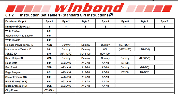
AHA! There they are, 9F as as JEDEC ID, so this is what we are looking for, I wonder what useful instruction can we do?
I can see the Read Data instruction there with opcode 03 , so I decided to just try it
# Example command
# jedec_id = exchange([0x9F], 3)
jedec_id = exchange([0x03], 3)
print(jedec_id)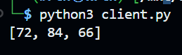
Whoa, it returns something! In fact, if we convert this to ASCII, it’s actually read HTB , so this could be the flag? Let’s try reading more data and see
# Example command
flag = exchange([0x03], 100)
print(bytes(flag))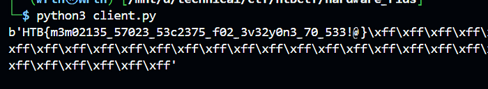
And we found the flag! But this is just the beginning, This client.py file will be used again in the challenge Flash-ing Logs, this challenges is here only to familiarize us with the client.py file and the manual. There are many things that we haven’t learned yet, like in the instruction, there are option to provide more than 1 bytes as the instruction, but at least our current knowledge is enough to solve this challenge
The PROM

This challenges uses a different hardware, that is AT28C16, an EEPROM, what is an EEPROM you ask? let’s see
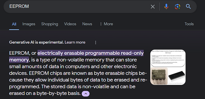
Okay so it’s pretty much the same thing as serial flash memory? We will discover more about the difference soon, this time we are given a remote connection but without any attachment, connecting to the service looks like this

This is interesting, and most importantly look, there are read_byte(), and write_byte() function, the description says that read_byte() reads something from the current address, what is the current address? it is controlled by the set_address_pins() function… right? maybe? anyway I don’t know anything about this, so let’s once again search for documentation
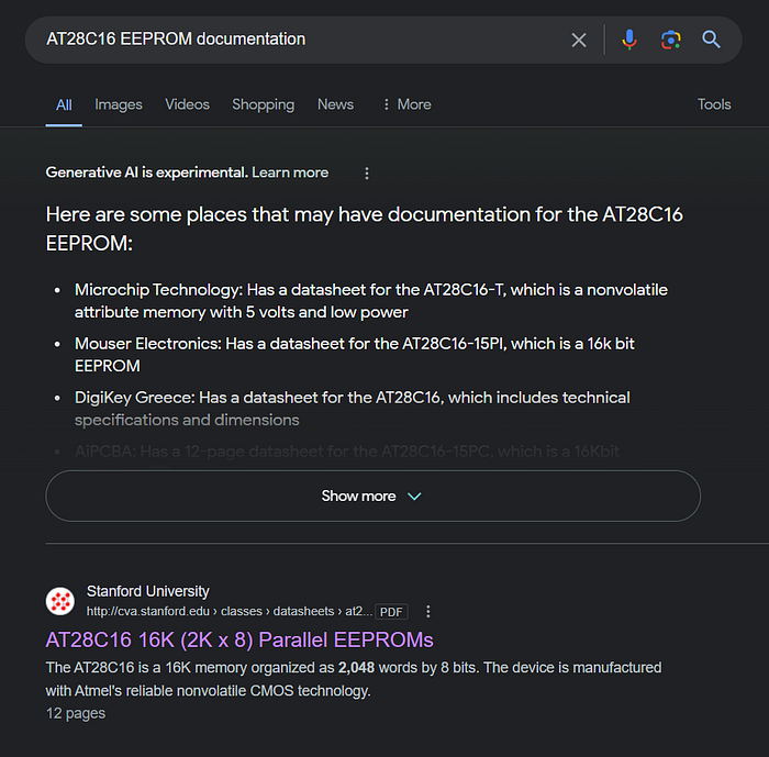
cool, once again we found a PDF, let’s read it
Oh no…. what does this even mean
Let’s do it like the previous challenge and attempt to read a byte from the memory, how can we do that?
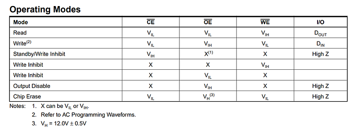
Let’s see the table right below that one
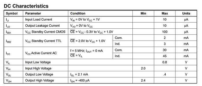
This clears things up a little, so in order to read, we have to set CE and OE pins to Input Low Voltage, meaning ≤ 0.8V, and set WE pins to Input High Voltage, that is > 2.0 V, but what there is 1 more column, the I/O column, what does D_out even mean? I can’t find it anywhere on the documentation, but let’s just skip it and see if it even matters
Alright, let’s try!
from pwn import *
# context.log_level = 'debug'
p = remote("94.237.57.59", 51883)

def read_mode():
    p.sendline(f"set_ce_pin(0.8)".encode())
    p.sendline(f"set_oe_pin(0.8)".encode())
    p.sendline(f"set_we_pin(2.0)".encode())

def read_byte():
    p.sendline(b'read_byte()')
    response = p.recvline().decode().strip()
    return response

p.recvuntil(b"4.2])")
p.recvline()
p.recvline()

read_mode()
print(read_byte())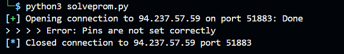
Oh no this is bad, we set the pins as it should be, but it still doesn’t work.
Looking at the notes below the flag
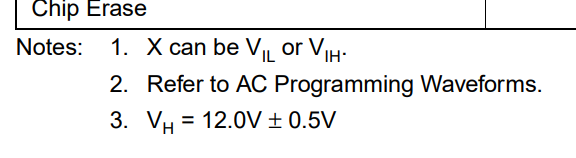
It says V_H is 12.0V, well its not exactly V_IH but what if we try? Also let’s lower the CE and OE pin a little bit, maybe if we put them in the middle it will be more stable?
from pwn import *
# context.log_level = 'debug'
p = remote("83.136.254.223", 52428)

def read_mode():
    p.sendline(f"set_ce_pin(0.5)".encode())
    p.sendline(f"set_oe_pin(0.5)".encode())
    p.sendline(f"set_we_pin(12)".encode())

def read_byte():
    p.sendline(b'read_byte()')
    response = p.recvline().decode().strip()
    return response

p.recvuntil(b"4.2])")
p.recvline()
p.recvline()

read_mode()
print(read_byte())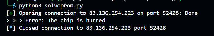
Well that didn’t work…
Okay so at this point I was just playing around trying to see what is the limit of voltage I can supply before the chip is burned, and then, this happened
from pwn import *
# context.log_level = 'debug'
p = remote("83.136.254.223", 52428)

def read_mode():
    p.sendline(f"set_ce_pin(0.5)".encode())
    p.sendline(f"set_oe_pin(0.5)".encode())
    p.sendline(f"set_we_pin(5)".encode())

def read_byte():
    p.sendline(b'read_byte()')
    response = p.recvline().decode().strip()
    return response

p.recvuntil(b"4.2])")
p.recvline()
p.recvline()

read_mode()
print(read_byte())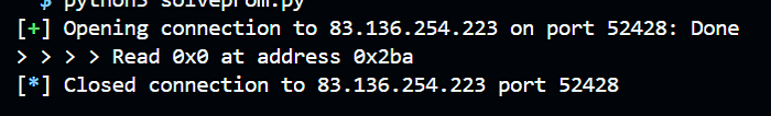
It works!
I set the WE pin to 5V and now we can read a byte, but we can see that it reads from an arbitrary address, how can we control the address?
Let’s read some more documentation

Okay so the location is determined by address pins, and we have the set_address_pins function, but how do we use it?
I tried to use it the same way to set the io pins but it shows the following error
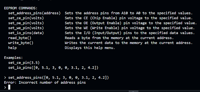
Okay so looking at the description of the commands the set_address_pins function sets the address pins from A10 to A0, so there will be in total 11 pins, so let’s try it!
# I will now not write the previous functions again so the snippet wouldn't take too much space
p.recvuntil(b"4.2])")
p.recvline()
p.recvline()

p.sendline(b"set_address_pins([0,0,0,0,0,0,0,0,0,0,0])")
read_mode()
print(read_byte())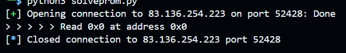
It works!
It also read at address 0, so I instinctively thinks this is binary, let’s try to read at index 1
p.sendline(b"set_address_pins([0,0,0,0,0,0,0,0,0,0,1])")
read_mode()
print(read_byte())
What?? its still read at address 0? How???
Learning from the previous mistake, we can try to increase the voltage again, and as expected somewhere around 10 volt will burn the chip, but setting it just right apparently allow us to now control the address
p.sendline(b"set_address_pins([0,0,0,0,0,0,0,0,0,0,5])")
read_mode()
print(read_byte())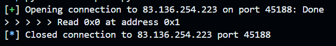
Yeay, now we can control the address!
Now we will modify our read_byte function to read at specific address
def to_address(num):
    address = bin(num)[2:].zfill(11)
    address = address.replace('1', '5')
    address = f"[{','.join(address)}]"
    return address

def read_byte(addr):
    address = to_address(addr)
    p.sendline(f"set_address_pins({address})".encode())
    p.sendline(b'read_byte()')
    response = p.recvline().decode().strip()
    return response
So now where should we read? unfortunately even if you bruteforce the entire address range from 0, there is no flag written in the memory.
Let’s read more stuff from the documentation
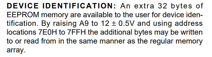
Okay, it looks like there are more stuff we can read by setting the A9 pins to 12V, let’s try it out!
We will add the new function to read from the secret address, This is what our script will look like
from pwn import *
# context.log_level = 'debug'
p = remote("83.136.254.223", 45188)

def read_mode():
    p.sendline(f"set_ce_pin(0.5)".encode())
    p.sendline(f"set_oe_pin(0.5)".encode())
    p.sendline(f"set_we_pin(5)".encode())

def to_address(num):
    address = bin(num)[2:].zfill(11)
    address = address.replace('1', '5')
    address = f"[{','.join(address)}]"
    return address

def read_byte(addr):
    address = to_address(addr)
    p.sendline(f"set_address_pins({address})".encode())
    p.sendline(b'read_byte()')
    response = p.recvline().decode().strip()
    return response

def to_address_secret(num):
    address = bin(num)[2:].zfill(5)
    address = list(address.replace('1', '5'))
    address = ['5','12','5','5','5','5'] + address
    address = f"[{','.join(address)}]"
    return address

def read_byte_secret(addr):
    address = to_address_secret(addr)
    p.sendline(f"set_address_pins({address})".encode())
    p.sendline(b'read_byte()')
    response = p.recvline().decode().strip()
    return response

p.recvuntil(b"4.2])")
p.recvline()
p.recvline()

read_mode()
print(read_byte_secret(0x0))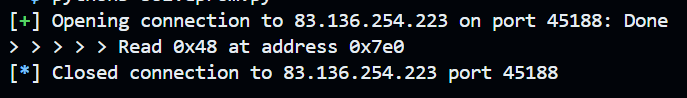
Looks like we have some data now! in fact, 0x48 is the letter H, which is the start of our flag, we can continue reading more bytes and get the full flag
read_mode()
for i in range(32):
    res = int((read_byte_secret(i)).split("Read ")[1].split()[0],16)
    print(chr(res), end="")
print()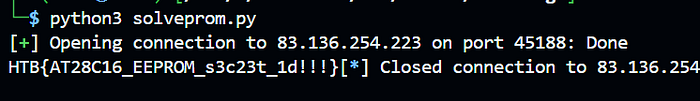
Flash-ing Logs
In this challenge we are back using W25Q128 and the client.py file from earlier. We are given the following C file
#include <stdio.h>
#include <stdint.h>
#include <stdbool.h>
#include <string.h>
#include <wiringPiSPI.h>
#include "W25Q128.h" // Our custom chip is compatible with the original W25Q128XX design

#define SPI_CHANNEL 0 // /dev/spidev0.0
//#define SPI_CHANNEL 1 // /dev/spidev0.1

#define CRC_SIZE 4 // Size of the CRC data in bytes
#define KEY_SIZE 12 // Size of the key


// SmartLockEvent structure definition
typedef struct {
    uint32_t timestamp;   // Timestamp of the event
    uint8_t eventType;    // Numeric code for type of event // 0 to 255 (0xFF)
    uint16_t userId;      // Numeric user identifier // 0 t0 65535 (0xFFFF)
    uint8_t method;       // Numeric code for unlock method
    uint8_t status;       // Numeric code for status (success, failure)
} SmartLockEvent;


// Function Prototypes
int log_event(const SmartLockEvent event, uint32_t sector, uint32_t address);
uint32_t calculateCRC32(const uint8_t *data, size_t length);
void write_to_flash(uint32_t sector, uint32_t address, uint8_t *data, size_t length);

// CRC-32 calculation function
uint32_t calculateCRC32(const uint8_t *data, size_t length) {
    uint32_t crc = 0xFFFFFFFF;
    for (size_t i = 0; i < length; ++i) {
        crc ^= data[i];
        for (uint8_t j = 0; j < 8; ++j) {
            if (crc & 1)
                crc = (crc >> 1) ^ 0xEDB88320;
            else
                crc >>= 1;
        }
    }
    return ~crc;
}


bool verify_flashMemory() {
    uint8_t jedc[3];
    uint8_t uid[8];
    uint8_t buf[256];
    uint8_t wdata[26];
    uint8_t i;

    uint16_t n;

    bool jedecid_match = true; // Assume true, prove false
    bool uid_match = true; // Assume true, prove false

    // JEDEC ID to verify against
    uint8_t expectedJedec[3] = {0xEF, 0x40, 0x18};

    // UID to verify against
    uint8_t expectedUID[8] = {0xd2, 0x66, 0xb4, 0x21, 0x83, 0x1f, 0x09, 0x2b};


    // SPI channel 0 at 2MHz.
    // Start SPI channel 0 with 2MHz
    if (wiringPiSPISetup(SPI_CHANNEL, 2000000) < 0) {
      printf("SPISetup failed:\n");
    }

    // Start Flash Memory
    W25Q128_begin(SPI_CHANNEL);

    // JEDEC ID Get
    //W25Q128_readManufacturer(buf);
    W25Q128_readManufacturer(jedc);
    printf("JEDEC ID : ");
    for (i=0; i< 3; i++) {
      printf("%x ",jedc[i]);
    }

    // Iterate over the array and compare elements
    for (int i = 0; i < sizeof(jedc)/sizeof(jedc[0]); ++i) {
        if (jedc[i] != expectedJedec[i]) {
            jedecid_match = false; // Set match to false if any element doesn't match
            break; // No need to check further if a mismatch is found
        }
    }

    if (jedecid_match) {
        printf("JEDEC ID verified successfully.\n");
    } else {
        printf("JEDEC ID does not match.\n");
        return 0;
    }

    // Unique ID
    // Unique ID Get
    W25Q128_readUniqieID(uid);
    printf("Unique ID : ");
    for (i=0; i< 8; i++) {
      printf("%x ",uid[i]);
    }
    printf("\n");

    // Iterate over the array and compare elements
    for (int i = 0; i < sizeof(uid)/sizeof(uid[0]); ++i) {
        if (uid[i] != expectedUID[i]) {
            uid_match = false; // Set match to false if any element doesn't match
            break; // No need to check further if a mismatch is found
        }
    }

    if (uid_match) {
        printf("UID verified successfully.\n");
    } else {
        printf("UID does not match.\n");
        return 0;
    }

    return 1;
}
// Implementations
int log_event(const SmartLockEvent event, uint32_t sector, uint32_t address) {

    bool memory_verified = false;
    uint8_t i;
    uint16_t n;
    uint8_t buf[256];


    memory_verified = verify_flashMemory();
    if (!memory_verified) return 0;

     // Start Flash Memory
    W25Q128_begin(SPI_CHANNEL);

    // Erase data by Sector
    if (address == 0){
        printf("ERASE SECTOR!");
        n = W25Q128_eraseSector(0, true);
        printf("Erase Sector(0): n=%d\n",n);
        memset(buf,0,256);
        n =  W25Q128_read (0, buf, 256);

    }

    uint8_t buffer[sizeof(SmartLockEvent) + sizeof(uint32_t)]; // Buffer for event and CRC
    uint32_t crc;

    memset(buffer, 0, sizeof(SmartLockEvent) + sizeof(uint32_t));

    // Serialize the event
    memcpy(buffer, &event, sizeof(SmartLockEvent));

    // Calculate CRC for the serialized event
    crc = calculateCRC32(buffer, sizeof(SmartLockEvent));

    // Append CRC to the buffer
    memcpy(buffer + sizeof(SmartLockEvent), &crc, sizeof(crc));


    // Print the SmartLockEvent for debugging
    printf("SmartLockEvent:\n");
    printf("Timestamp: %u\n", event.timestamp);
    printf("EventType: %u\n", event.eventType);
    printf("UserId: %u\n", event.userId);
    printf("Method: %u\n", event.method);
    printf("Status: %u\n", event.status);

    // Print the serialized buffer (including CRC) for debugging
    printf("Serialized Buffer (including CRC):");
    for (size_t i = 0; i < sizeof(buffer); ++i) {
        if (i % 16 == 0) printf("\n"); // New line for readability every 16 bytes
        printf("%02X ", buffer[i]);
    }
    printf("\n");


    // Write the buffer to flash
    write_to_flash(sector, address, buffer, sizeof(buffer));


    // Read 256 byte data from Address=0
    memset(buf,0,256);
    n =  W25Q128_read(0, buf, 256);
    printf("Read Data: n=%d\n",n);
    dump(buf,256);

    return 1;
}


// encrypts log events
void encrypt_data(uint8_t *data, size_t data_length, uint8_t register_number, uint32_t address) {
    uint8_t key[KEY_SIZE];

    read_security_register(register_number, 0x52, key); // register, address

    printf("Data before encryption (including CRC):\n");
    for(size_t i = 0; i < data_length; ++i) {
        printf("%02X ", data[i]);
    }
    printf("\n");

    // Print the CRC32 checksum before encryption (assuming the original data includes CRC)
    uint32_t crc_before_encryption = calculateCRC32(data, data_length - CRC_SIZE);
    printf("CRC32 before encryption: 0x%08X\n", crc_before_encryption);

    // Apply encryption to data, excluding CRC, using the key
    for (size_t i = 0; i < data_length - CRC_SIZE; ++i) { // Exclude CRC data from encryption
        data[i] ^= key[i % KEY_SIZE]; // Cycle through  key bytes
    }

    printf("Data after encryption (including CRC):\n");
    for(size_t i = 0; i < data_length; ++i) {
        printf("%02X ", data[i]);
    }
    printf("\n");


}

void write_to_flash(uint32_t sector, uint32_t address, uint8_t *data, size_t length) {
    printf("Writing to flash at sector %u, address %u\n", sector, address);

    uint8_t i;
    uint16_t n;

    encrypt_data(data, length, 1, address);

    n =  W25Q128_pageWrite(sector, address, data, 16);
    printf("page_write(0,10,d,26): n=%d\n",n);

}
Time to actually learn about the instructions
Before we get into solving the challenge, we will learn how to read and write from the memory, as previously we are very lucky to be able to solve the challenge by barely knowing about the instructions, this time we really need to dive deep
The first step that we gonna do is reading from a particular address, at the previous challenge all we need to do is to read without specifying the location (presumably address 0), but this time let’s really try to understand how to do this properly
The only time consuming part about the challenge is just reading documentation again and again, I don’t think I need to go indepth on how to read documentation anymore, anyway we can see how we can read from a specific address here.
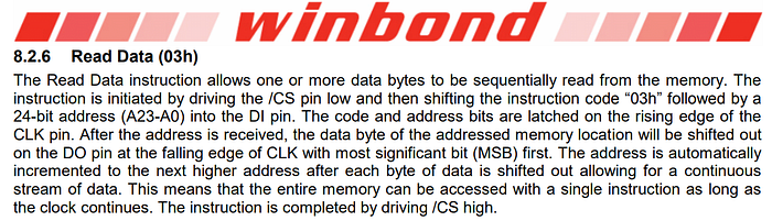
So it’s not that difficult really, just 03 followed by 24 bit address, which is 3 byte
from pwn import *
import socket
import json

FLAG_ADDRESS = [0x52, 0x52, 0x52]

def exchange(hex_list, value=0):

    # Configure according to your setup
    host = '94.237.54.164'  # The server's hostname or IP address
    port = 37972        # The port used by the server
    cs=0 # /CS on A*BUS3 (range: A*BUS3 to A*BUS7)

    usb_device_url = 'ftdi://ftdi:2232h/1'

    # Convert hex list to strings and prepare the command data
    command_data = {
        "tool": "pyftdi",
        "cs_pin":  cs,
        "url":  usb_device_url,
        "data_out": [hex(x) for x in hex_list],  # Convert hex numbers to hex strings
        "readlen": value
    }

    with socket.socket(socket.AF_INET, socket.SOCK_STREAM) as s:
        s.connect((host, port))

        # Serialize data to JSON and send
        s.sendall(json.dumps(command_data).encode('utf-8'))

        # Receive and process response
        data = b''
        while True:
            data += s.recv(1024)
            if data.endswith(b']'):
                break
            # print(data)

        response = json.loads(data.decode('utf-8'))
        #print(f"Received: {response}")
    return response

# ===== NEW ======
def read_data(addr, length, quiet=False):
    if type(addr) != list:
        # split the address into 3 bytes
        addr = [addr >> 16, addr >> 8 & 0xff, addr & 0xff]
    res = exchange([0x03]+addr, length)
    if not quiet:
        print("read:",[hex(x) for x in res])
    return res

print(bytes(read_data(FLAG_ADDRESS, 100)))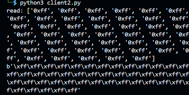
curently, reading the flag address will not give us anything, this is because we haven’t done the objective yet
Now let’s try writing, for our experiment we will also try to write to the flag address, we will write some data and read it to see if it works
It’s so frustrating to not be able to find the words “Write Data” at the documentation, quick google search will say that write data uses opcode 02, which if we check on the datasheet is indeed writing data but have a very unintuitive name
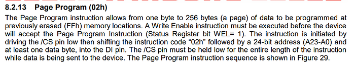
Okay so in order to be able to write, the data must be erased (is 0xFF), and also we have to call a write enable instruction before doing it. Reading the documentation tells us that Write Enable instruction is at 0x06
def write_enable():
    x = exchange([0x06], 100)
    # print([hex(x) for x in x])
    return

def write_data(addr, data):
    write_enable()
    if type(addr) != list:
        # split the address into 3 bytes
        addr = [addr >> 16, addr >> 8 & 0xff, addr & 0xff]
    x = exchange([0x02]+addr+data, 100)
    print("write:",data)
    return

print(bytes(read_data(FLAG_ADDRESS, 10)))
write_data(FLAG_ADDRESS, [0x42]*10)
print(bytes(read_data(FLAG_ADDRESS, 10)))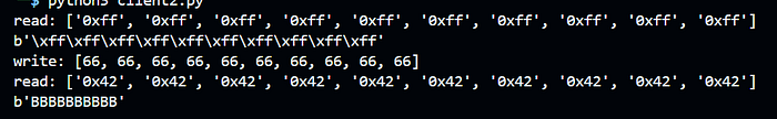
Cool! Now we can read and write data, but remember that the documentation said that we can only write when the memory is at 0xFF, a quick google search will tell you that it’s because the instruction is only turning off the on switch and not vice versa, so for example we can write 101 from 111 by turning off the second bit, but we can’t do it vice versa
So now the last basic instruction we need to learn about is the erase instruction
Looking at the datasheet, this is the only thing I can find about erasing

It appears that we can’t erase an individual memory, we have to erase the entire sector, which is the range of 4KB, but needless to say let’s give it a try
def erase_data(addr):
    write_enable()
    if type(addr) != list:
        # split the address into 3 bytes
        addr = [addr >> 16, addr >> 8 & 0xff, addr & 0xff]
    x = exchange([0x20]+addr, 10)
    print("erase:",[hex(x) for x in x])
    return

read_data(FLAG_ADDRESS, 10)
write_data(FLAG_ADDRESS, [0x42]*10)
read_data(FLAG_ADDRESS, 10)
erase_data(FLAG_ADDRESS)
read_data(FLAG_ADDRESS, 10)
Looks good to me!
Understanding the challenge
Now that we can manipulate the memory from the client, we can now starts to understand how the challenge is structured, from the description, it says that it write some logs into the memory, and we have to overwrite some logs to cover our tracks. but if you read the memory starting from address 0, it’s all gibberish, let’s see how the logs are written.
int log_event(const SmartLockEvent event, uint32_t sector, uint32_t address) {

    bool memory_verified = false;
    uint8_t i;
    uint16_t n;
    uint8_t buf[256];


    memory_verified = verify_flashMemory();
    if (!memory_verified) return 0;

     // Start Flash Memory
    W25Q128_begin(SPI_CHANNEL);

    // Erase data by Sector
    if (address == 0){
        printf("ERASE SECTOR!");
        n = W25Q128_eraseSector(0, true);
        printf("Erase Sector(0): n=%d\n",n);
        memset(buf,0,256);
        n =  W25Q128_read (0, buf, 256);

    }

    uint8_t buffer[sizeof(SmartLockEvent) + sizeof(uint32_t)]; // Buffer for event and CRC
    uint32_t crc;

    memset(buffer, 0, sizeof(SmartLockEvent) + sizeof(uint32_t));

    // Serialize the event
    memcpy(buffer, &event, sizeof(SmartLockEvent));

    // Calculate CRC for the serialized event
    crc = calculateCRC32(buffer, sizeof(SmartLockEvent));

    // Append CRC to the buffer
    memcpy(buffer + sizeof(SmartLockEvent), &crc, sizeof(crc));


    // Print the SmartLockEvent for debugging
    printf("SmartLockEvent:\n");
    printf("Timestamp: %u\n", event.timestamp);
    printf("EventType: %u\n", event.eventType);
    printf("UserId: %u\n", event.userId);
    printf("Method: %u\n", event.method);
    printf("Status: %u\n", event.status);

    // Print the serialized buffer (including CRC) for debugging
    printf("Serialized Buffer (including CRC):");
    for (size_t i = 0; i < sizeof(buffer); ++i) {
        if (i % 16 == 0) printf("\n"); // New line for readability every 16 bytes
        printf("%02X ", buffer[i]);
    }
    printf("\n");


    // Write the buffer to flash
    write_to_flash(sector, address, buffer, sizeof(buffer));


    // Read 256 byte data from Address=0
    memset(buf,0,256);
    n =  W25Q128_read(0, buf, 256);
    printf("Read Data: n=%d\n",n);
    dump(buf,256);

    return 1;
}

void encrypt_data(uint8_t *data, size_t data_length, uint8_t register_number, uint32_t address) {
    uint8_t key[KEY_SIZE];

    read_security_register(register_number, 0x52, key); // register, address

    printf("Data before encryption (including CRC):\n");
    for(size_t i = 0; i < data_length; ++i) {
        printf("%02X ", data[i]);
    }
    printf("\n");

    // Print the CRC32 checksum before encryption (assuming the original data includes CRC)
    uint32_t crc_before_encryption = calculateCRC32(data, data_length - CRC_SIZE);
    printf("CRC32 before encryption: 0x%08X\n", crc_before_encryption);

    // Apply encryption to data, excluding CRC, using the key
    for (size_t i = 0; i < data_length - CRC_SIZE; ++i) { // Exclude CRC data from encryption
        data[i] ^= key[i % KEY_SIZE]; // Cycle through  key bytes
    }

    printf("Data after encryption (including CRC):\n");
    for(size_t i = 0; i < data_length; ++i) {
        printf("%02X ", data[i]);
    }
    printf("\n");


}

void write_to_flash(uint32_t sector, uint32_t address, uint8_t *data, size_t length) {
    printf("Writing to flash at sector %u, address %u\n", sector, address);

    uint8_t i;
    uint16_t n;

    encrypt_data(data, length, 1, address);

    n =  W25Q128_pageWrite(sector, address, data, 16);
    printf("page_write(0,10,d,26): n=%d\n",n);

}
The flow is not as difficult as it looks, here is some high level explanation
1. The logs are in a form of a struct
2. The struct are written into a buffer
3. Calculate the CRC of the buffer and append it to the end of the buffer
4. The buffer (not including the CRC) is xored by a static key taken from the security register
5. The buffer and the CRC is written to the memory in block of 16
If analyzing this feels hard for you, its okay, I myself spent hours just trying to understand the source code, I tried my best to summarize stuff along the way so we doesn’t waste too much time
Before we continue, we must learn another new instruction, that is the Read Security Register instruction, this instruction reads from a register, which probably has the same concept as regular executable register. Looking at the documentation we can see that the Read Security Register uses opcode 0x48
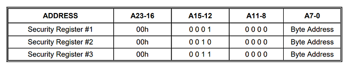
In the C file we know that we want to read from Security Register #1 from address 0x52, so lets do it
def read_security_register(addr, length):
    x = exchange([0x48]+[0,0b0001_0000,addr], length)
    print([hex(x) for x in x])
    return x

key = bytes(read_security_register(0x52, 12))+b"\x00"*4
Remember that the CRC does not get XORed, thus I set the last 4 bytes of the key to be null
With all our knowledge now this has become a regular reversing challenge, all we need is just patients to slowly analyzing the code and implement it.
Now we can write a parser for the logs, it reads from the memory, XOR it with the key, and parse its struct structure and the CRC
def get_crc(data):
    crc = 0xFFFFFFFF
    for i in range(len(data)):
        crc ^= data[i]
        for j in range(8):
            if crc & 1:
                crc = (crc >> 1) ^ 0xEDB88320
            else:
                crc >>= 1
    return crc ^ 0xFFFFFFFF

def parse_event(event):
    timestamp = event[0:4]
    eventType = event[4]
    userId = event[6:8] # this might look odd, but after experimenting in C this is exactly how the struct is converted into the buffer, idk why
    method = event[8]
    status = event[9]
    crcs = event[-4:]
    computed_crc = get_crc(event[0:-4]).to_bytes(4, "little")
    print({
        "timestamp": (int.from_bytes(timestamp, "little")),
        "eventType": eventType,
        "userId": hex(int.from_bytes(userId, "little")),
        "method": method,
        "status": status
    })
    assert computed_crc == crcs
    print("CRC OK")

def read_and_parse_event(idx, amount=1):
    res = bytes(read_data(16*idx, 16*amount))
    structs = (xor(res,key))
    structs = [structs[i:i+16] for i in range(0, len(structs), 16)]
    events = []
    for _,i in enumerate(structs):
        print(_, end=' ')
        parse_event(i)
        events.append(i)
    return events

read_and_parse_event(0, amount=10)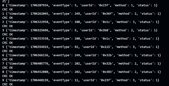
This looks really really promising, the timestamp is strictly increasing, the status and method stays low, and the CRC matches. We are on the right path
Now it’s time to find which logs contains our userId, 0x5244. After reading at all the logs I finally found our user logs at the last 4 log, that is at index 156–160
read_and_parse_event(156, amount=4)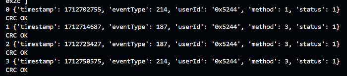
Putting Everything Together
So now all we need is to change this particular log, remember, we cannot change any other log, only this 4 logs, also there are CRC checking which means that we have to recalculate the CRC as well, this is no issue as we already implemented the CRC function ourself.
We already learn about reading, writing, and erasing data. Remember that erasing data can only be done in sectors. This means that we will clear the entire logs, rewrite old logs, and then write our new modified logs only at index 156–160
After putting everything together, this is what our final script will look like
from pwn import *
import socket
import json

FLAG_ADDRESS = [0x52, 0x52, 0x52]
START = 156
LOG_LEN = 16
LOGS_AMOUNT = 4

def exchange(hex_list, value=0):

    # Configure according to your setup
    host = '94.237.54.170'  # The server's hostname or IP address
    port = 54714        # The port used by the server
    cs=0 # /CS on A*BUS3 (range: A*BUS3 to A*BUS7)

    usb_device_url = 'ftdi://ftdi:2232h/1'

    # Convert hex list to strings and prepare the command data
    command_data = {
        "tool": "pyftdi",
        "cs_pin":  cs,
        "url":  usb_device_url,
        "data_out": [hex(x) for x in hex_list],  # Convert hex numbers to hex strings
        "readlen": value
    }

    with socket.socket(socket.AF_INET, socket.SOCK_STREAM) as s:
        s.connect((host, port))

        # Serialize data to JSON and send
        s.sendall(json.dumps(command_data).encode('utf-8'))

        # Receive and process response
        data = b''
        while True:
            data += s.recv(1024)
            if data.endswith(b']'):
                break
            # print(data)

        response = json.loads(data.decode('utf-8'))
        #print(f"Received: {response}")
    return response

def write_enable():
    x = exchange([0x06], 100)
    # print([hex(x) for x in x])
    return

def read_data(addr,length,quiet=False):
    if type(addr) != list:
        # split the address into 3 bytes
        addr = [addr >> 16, addr >> 8 & 0xff, addr & 0xff]
    jedec_id = exchange([0x03]+addr, length)
    if not quiet:
        print("read:",[hex(x) for x in jedec_id])
    return jedec_id

def erase_data(addr):
    write_enable()
    if type(addr) != list:
        # split the address into 3 bytes
        addr = [addr >> 16, addr >> 8 & 0xff, addr & 0xff]
    x = exchange([0x20]+addr, 10)
    print("erase:",[hex(x) for x in x])
    return

def write_data(addr, data):
    write_enable()
    if type(addr) != list:
        # split the address into 3 bytes
        addr = [addr >> 16, addr >> 8 & 0xff, addr & 0xff]
    x = exchange([0x02]+addr+data, 100)
    print("write:",data)
    return

def read_security_register(addr, length):
    x = exchange([0x48]+[0,0b0001_0000,addr], length)
    print([hex(x) for x in x])
    return x

def get_crc(data):
    crc = 0xFFFFFFFF
    for i in range(len(data)):
        crc ^= data[i]
        for j in range(8):
            if crc & 1:
                crc = (crc >> 1) ^ 0xEDB88320
            else:
                crc >>= 1
    return crc ^ 0xFFFFFFFF

def parse_event(event):
    timestamp = event[0:4]
    eventType = event[4]
    userId = event[6:8]
    method = event[8]
    status = event[9]
    crcs = event[-4:]
    computed_crc = get_crc(event[0:-4]).to_bytes(4, "little")
    print({
        "timestamp": (int.from_bytes(timestamp, "little")),
        "eventType": eventType,
        "userId": hex(int.from_bytes(userId, "little")),
        "method": method,
        "status": status
    })
    assert computed_crc == crcs
    print("CRC OK")

key = bytes(read_security_register(0x52, 12))+b"\x00"*4
def read_and_parse_event(idx, amount=1):
    res = bytes(read_data(16*idx, 16*amount))
    structs = (xor(res,key))
    structs = [structs[i:i+16] for i in range(0, len(structs), 16)]
    events = []
    for _,i in enumerate(structs):
        print(_, end=' ')
        parse_event(i)
        events.append(i)
    return events

def change_user_id_and_recalc_crc(event, new_id):
    event = bytearray(event)
    print("old", end=' ')
    parse_event(event)
    event[6:8] = new_id.to_bytes(2, "little")
    event[-4:] = get_crc(event[0:-4]).to_bytes(4, "little")
    try:
        print("new", end=' ')
        parse_event(event)
    except:
        print('MISMATCH!')
    return event

print("Sanity check, reading the flag")
print(bytes(read_data(FLAG_ADDRESS, 100)))
print("---")

print("Sanity check, checking first event")
read_and_parse_event(0)
print("---")

old_data = read_data(0, START*LOG_LEN, quiet=True)
old_data = [old_data[i:i+128] for i in range(0, len(old_data), 128)]
to_write = read_and_parse_event(START, LOGS_AMOUNT)

input("Press enter to continue to recalculate crc")
for i in range(LOGS_AMOUNT):
    to_write[i] = xor(change_user_id_and_recalc_crc(to_write[i], 0x1337), key)

input("Press enter to continue to write")
erase_data(0)
for i in range(len(old_data)):
    write_data(i*128, list(old_data[i]))

print("Old data has been restored")
print("Sanity check, checking first event")
read_and_parse_event(0)

print("Now writing modified logs")
for i in range(LOGS_AMOUNT):
    write_data((START+i)*LOG_LEN, list(to_write[i]))

print(bytes(read_data(FLAG_ADDRESS, 100)))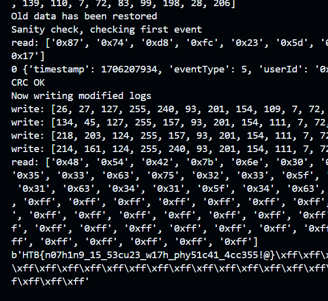
And there you have it! We have conquered the entirety of hardware category without any prior knowledge of hardware. If you have any question feel free to reach out to me @wrth via discord :)